Choose a conventional active RC filter when a stable response, low circuit complexity, or a demanding noise and distortion budget favors a purpose-built analog design. Consider a switched-capacitor filter when repeatable frequency control, higher-order integration, or changing bandwidth makes that architecture useful. The right choice depends on the complete signal chain, including its interfaces and clocks.
Our Chameleon overview introduces the module platform. This guide focuses on the engineering decision: what each approach simplifies, what it adds, and how to compare them fairly.
Define the response before choosing the circuit
Start with the useful signal bandwidth, permissible passband loss, required stopband attenuation, signal amplitude, noise budget, and acceptable settling time. For an ADC input, include the sampling plan and frequencies that can alias into the retained measurement band.
Our companion article, Anti-Aliasing Filter Design for ADCs: Choosing Cutoff Frequency and Filter Order, develops those requirements through a worked example. Once the response is defined, compare circuits capable of meeting the same requirements. A fourth-order Butterworth filter and an eighth-order elliptic filter differ in much more than implementation technology.
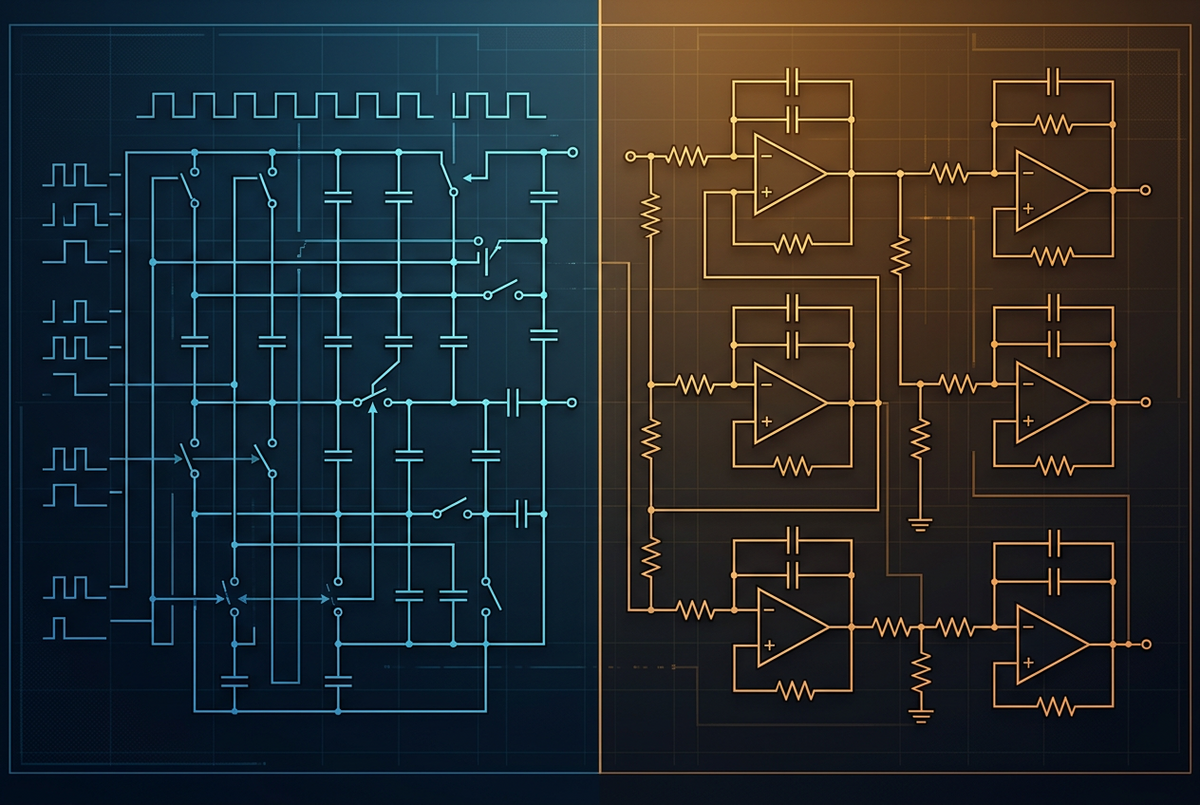
Also separate the response family from the architecture. Butterworth, Bessel, Chebyshev, and elliptic describe response characteristics. Active RC and switched-capacitor describe ways to realize a response. A switched-capacitor implementation is still an active analog circuit; the distinction here is sampled analog operation versus conventional continuous-time RC filtering.
How a switched-capacitor filter works
A conventional active RC filter combines amplifiers, resistors, and capacitors. Its poles and gain depend on the component values, circuit topology, and amplifier behavior.
In a simplified switched-capacitor circuit, clocked switches repeatedly transfer charge between nodes. A capacitor transferring charge proportional to a voltage difference produces an average current. Under the ideal approximation, its equivalent resistance is:
Increasing the switching frequency reduces this equivalent resistance. In a filter, clock frequency and capacitor ratios can therefore establish the time constants. Integrated capacitor matching helps make the response repeatable without requiring a large external precision RC network.
The signal remains analog in amplitude, but the circuit processes it at discrete times. That introduces sampling-related constraints, including aliasing and switching artifacts. A switched-capacitor filter is not a digital filter, and it is not inherently an ADC.
Compare the complete implementations
These are selection considerations, not universal rankings. Texas Instruments’ Active Low-Pass Filter Design provides background on the underlying trade-offs.
Understand what frequency accuracy does and does not guarantee
Consider a simple RC pole with a nominal frequency of 10 kHz. If R has a ±1% tolerance and C has a ±5% tolerance, the ideal relation between pole frequency and the RC product gives worst-case limits of approximately 9.43–10.63 kHz. This is a calculated tolerance example, not a measurement of a particular active filter.
It also is not a prediction for every high-order RC design. Different topologies have different sensitivities, especially for Q. Precision components, matched networks, calibration, and careful topology selection can substantially improve performance.
For comparison, the Chameleon OTC931xL eighth-order filter datasheet lists 0.1% typical and 0.5% maximum frequency accuracy at 25°C. That is a product specification, not a general accuracy claim for all switched-capacitor filters.
Frequency accuracy also does not establish absolute gain accuracy, distortion, or noise performance. Evaluate those separately at the intended signal amplitude, temperature, supply, and load.
Compare noise and clock artifacts separately
A useful comparison needs both a noise measurement and a spectrum. A single RMS number can hide discrete clock-related tones, while a spur-free plot may omit noise outside the displayed band.
For both architectures, specify the measurement bandwidth, gain, input termination, output loading, and any downstream filtering. Compare distortion at the same input amplitude and frequency. For switched-capacitor circuits, include the clock frequency, clock relationships, and whether clock spurs remain in the reported result.
The OTC931xL datasheet lists 200 µV RMS wideband noise under its stated test conditions, including interface stages, with sample-clock components and harmonics removed. It should not be treated as an unfiltered output-noise guarantee or compared directly with an op amp’s noise density in nV/√Hz.
At the input, continuous-time filtering may be needed to keep high-frequency signals from aliasing inside the switched-capacitor stage. At the output, smoothing may be needed to suppress switching artifacts before a downstream ADC. Synchronization can improve sampling timing, but it does not automatically eliminate every spur or offset.
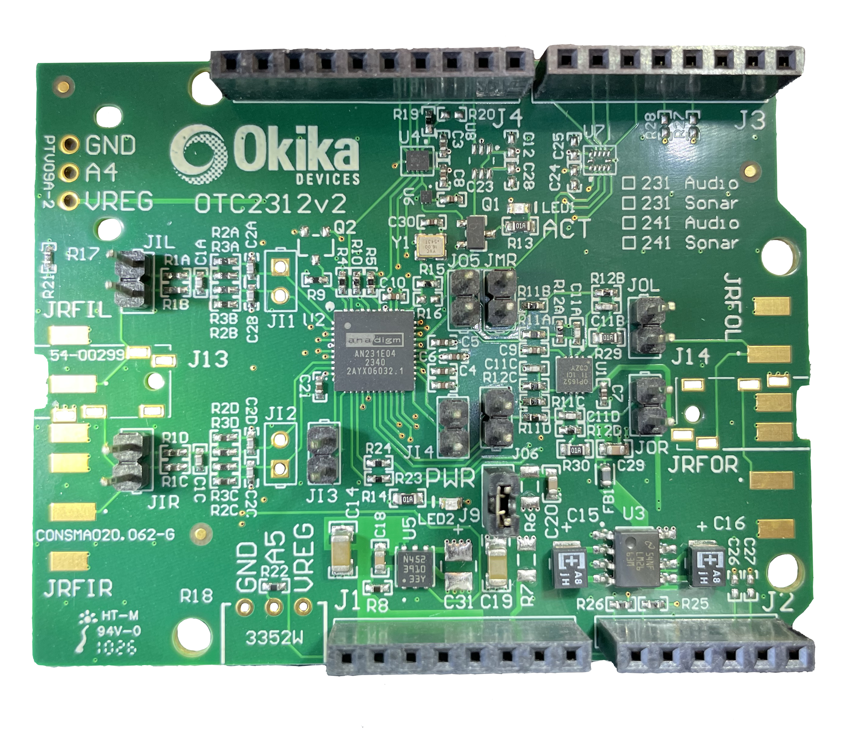
The Chameleon datasheet describes a spare amplifier for Rauch output smoothing. Okika’s FlexAnalog interfacing guide also explains input filtering and level translation. The resulting implementation can combine active RC interfaces with a switched-capacitor core.
When active RC is the better choice
The requirement is simple and fixed. A low-order filter with one permanent cutoff may need only a small RC network and an appropriate amplifier. Programmable hardware may add unnecessary power, cost, or validation effort.
The spur, noise, or distortion budget is especially tight. A continuous-time design avoids internally generated sampling-clock feedthrough. It also gives the engineer direct control over amplifier selection, resistor noise, capacitor type, and signal swing. Whether it meets the budget still requires analysis and measurement.
The application needs bandwidth or voltage range outside the candidate module’s limits. Discrete design offers a wider choice of supply rails, amplifiers, and interfaces. Check gain-bandwidth and slew rate at the required amplitude rather than relying on a small-signal bandwidth figure alone.
Only a few bandwidth settings are needed. Active RC does not have to mean permanently fixed. Switched resistor/capacitor banks or tunable integrators can provide several modes while preserving continuous-time operation between updates. Switching parasitics, charge injection during changes, and settling still need attention.
These cases make active RC a serious candidate, including in systems that use programmable analog elsewhere.
Distinguish three ways to use programmable analog
Factory-configured filter module
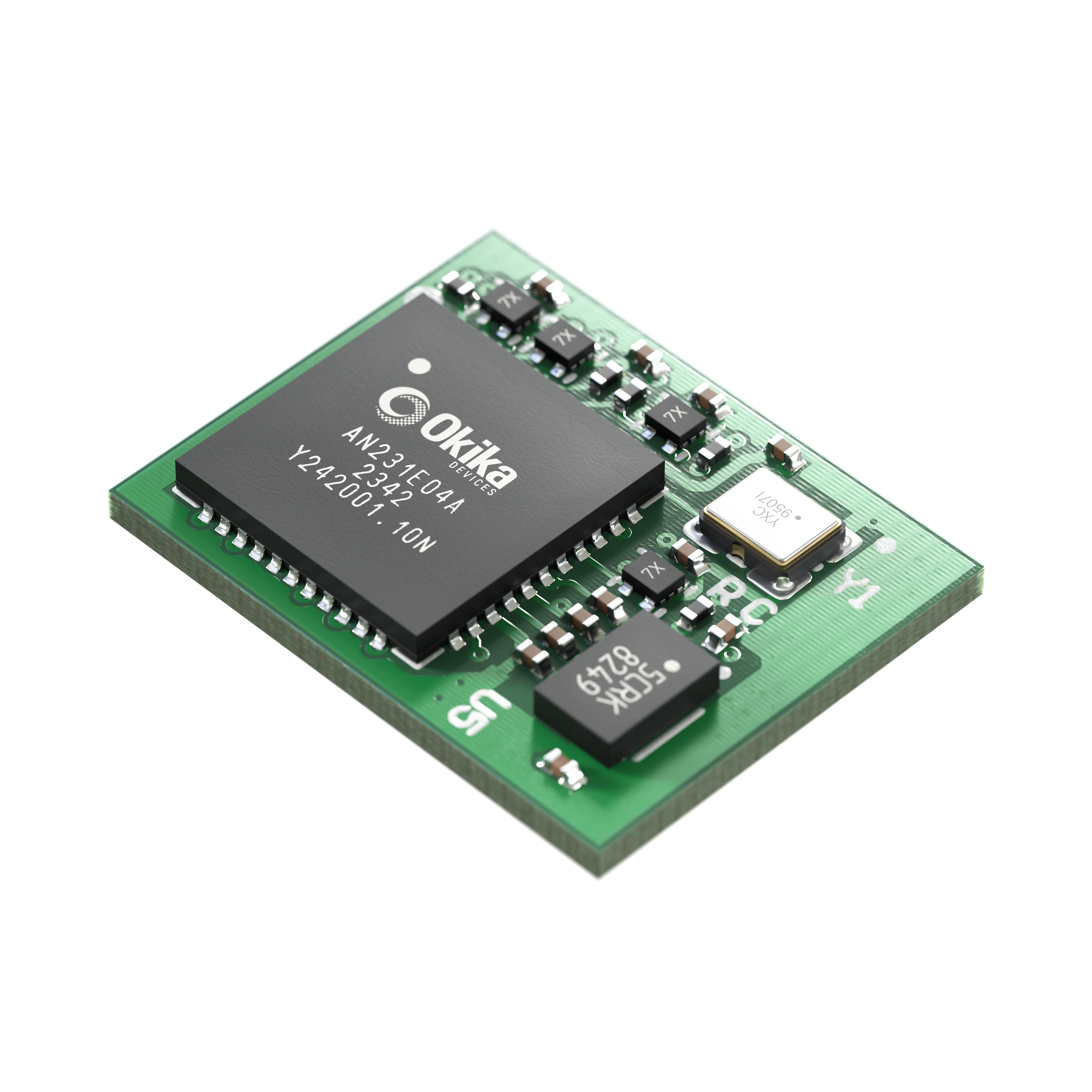
The Chameleon eighth-order Butterworth modules arrive with a stored configuration and an onboard clock. Standard cutoff options span 10 Hz to 100 kHz. In normal operation, the engineer uses a characterized fixed-function filter without managing runtime configuration.
An FPAA inside the package does not make the purchased module automatically adaptive. Intentional EEPROM reprogramming is supported, but a modified response needs its own validation.
User-programmed Chameleon module
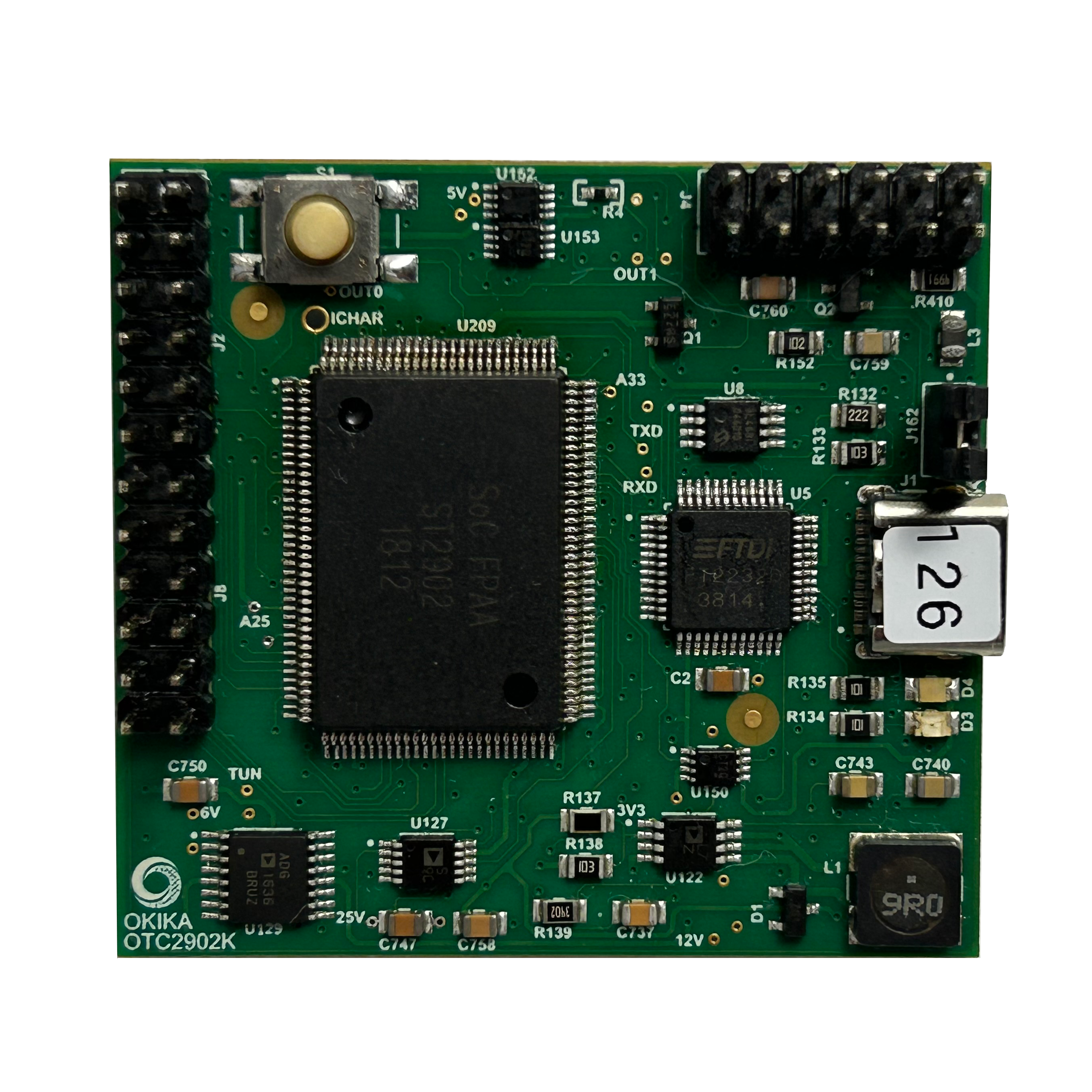
The OTC9300L programmable module is supplied blank. Engineers develop configurations in AnadigmDesigner2 and load them through a supported programming path. It should not be purchased as though it already contains a working application filter.
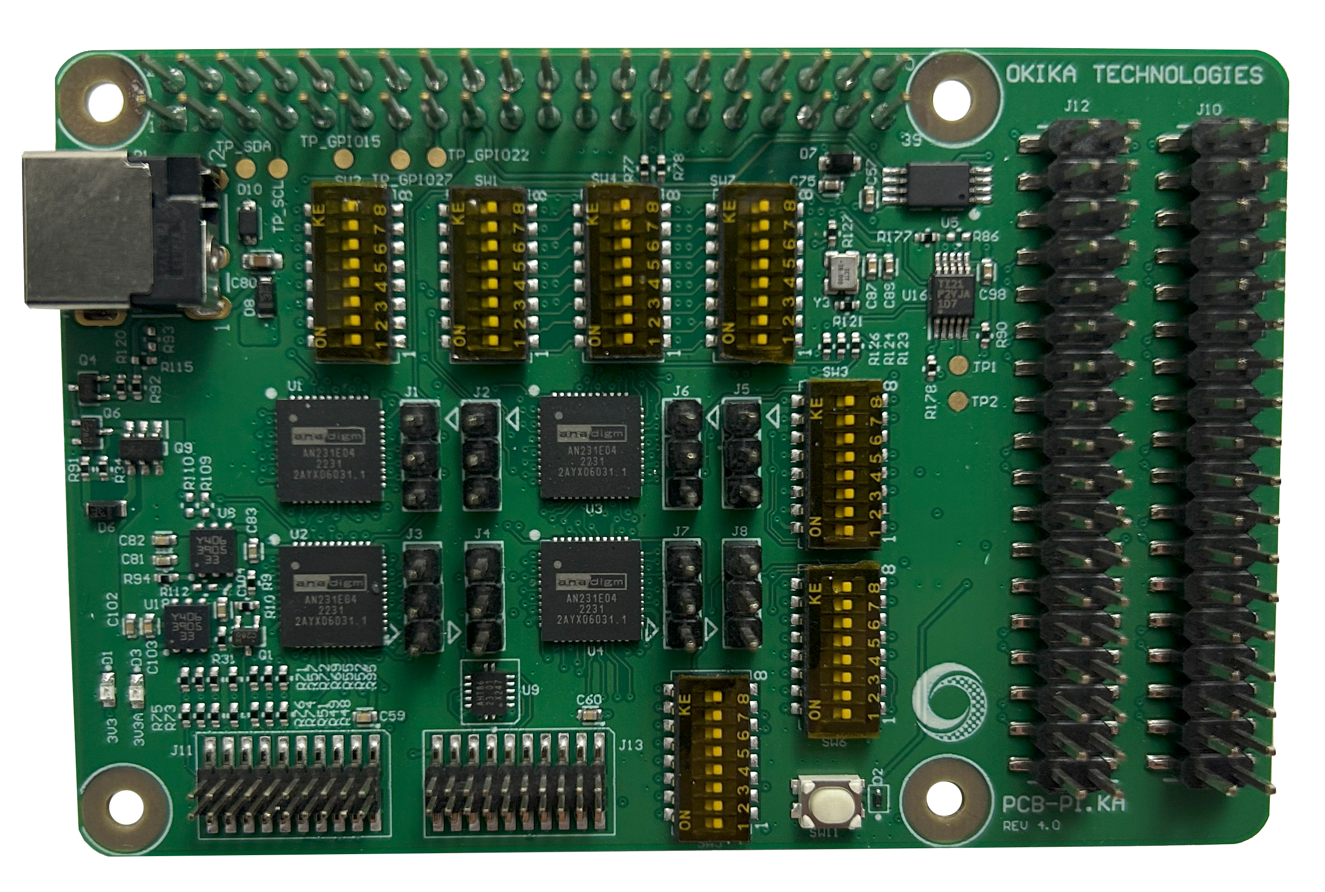
For bench programming and evaluation, the Chameleon Programming Board provides a socketed fixture and an interface for a compatible 3.3 V SPI EEPROM programmer or external controller. The fixture does not replace that programming source.
FPAA implementation designed for runtime changes
For frequent bandwidth or topology changes, design around a directly controlled FPAA and its supported reconfiguration mechanism. Okika recommends considering the chip-based approach for on-the-fly changes rather than treating module EEPROM updates as an equivalent runtime feature.
The system must load valid configurations, coordinate acquisition, and allow analog settling after a change. For the roles of configurable blocks, routing, and clocks, see How FPAAs Work: Configurable Analog Blocks, Routing, Clocks, and Dynamic Reconfiguration.
Do not confuse a configurable analog block’s bandwidth with a guaranteed complete filter response. The OTC9300L datasheet lists 400 kHz for selected filter CAMs under stated AN231 clock conditions; an assembled high-order filter, including its interfaces, must be evaluated in its actual configuration. [10]
Example of changing bandwidth on one sensor platform
Suppose a vibration instrument uses the same sensor and ADC for two modes: routine monitoring through 500 Hz and diagnostic capture through 5 kHz. Assume the ADC stays at 40 kS/s and the signal chain remains linear, with unity nominal gain.
To demonstrate the bandwidth decision, model a fourth-order Butterworth response with a 1 kHz cutoff in monitoring mode and a 10 kHz cutoff in diagnostic mode. The ideal attenuation is:
These are numerical frequency-response simulations of an ideal fourth-order analog Butterworth transfer function, checked against the equation above. They exclude component tolerances, amplifier nonidealities, sampled-data effects, and interface circuits. They are not measured Chameleon results. An ideal active RC realization of the same response produces the same numbers. The example illustrates the value of changing the response, not an intrinsic filtering advantage for either technology.
In monitoring mode, the narrower response reduces unwanted content before later stages. In diagnostic mode, the wider response retains vibration detail that monitoring would attenuate. For an input white-noise source, scaling the same ideal filter shape down by a factor of ten reduces its integrated output noise power by ten, or its RMS noise by about 3.16. This does not predict the filter’s own noise or noise within an unchanged digital measurement band.
With a runtime-programmable FPAA, the instrument can select validated configurations for these modes. A switched active RC network could also implement the two settings. Programmability becomes more valuable when additional sensors, gain settings, or response shapes must share the hardware.
Before deployment, determine anti-aliasing requirements for both modes using the method in the companion anti-aliasing article. The cutoff choices above do not establish sufficient rejection of every possible alias source. Check external input and output filters too: if a mode change lowers the internal switching frequency, interfaces sized for the faster mode may no longer provide adequate suppression.
Make the selection against the same acceptance criteria
Compare candidate circuits using the same passband, stopband, amplitude, noise, distortion, settling, power, and environmental limits. Include input conditioning, output smoothing, clock generation, firmware, and ADC drive in the cost and board-area comparison.
Active RC is often the practical choice for a stable, simple response or a tightly optimized analog path. A factory-configured Chameleon module fits a defined high-order filtering task. A user-programmable FPAA becomes useful when changing the analog response is part of the product’s operation or development strategy.
Choose the architecture that meets the complete specification with acceptable implementation and validation effort. The number of parts in the filter core is only one part of that decision.